Category Archive: Control Valves
Once Upon a Time This Valve Worked Well
Our process had to be shut down again. It seems that the original valve is no longer up to the task. Should I continue to simply repair the valve or should I look for another solution? Up until now, it was far easier to repair the valve and/or replace it in kind … but my process efficiencies are going down and I need to find a solution. Where do I start?
Changing Conditions
I pull out the valve data sheet and take a look at the original conditions. Wow! I can see immediately that things have changed –
- The plant has aged nearly 20 years;
- We replaced the pump on that line 5 years ago;
- We have modified the piping in the area of the valve;
- We changed the fluid chemistry;
- Instead of operating continuously, the plant is now cycling
Every time conditions change, we need to review the impact upon the control system.
Aging Systems
As a system ages, it does not get any cleaner. Whether it is due to pipe scale or there is other sediment in the system, a valve that worked in a clean system may not work as well in the older system. We have periodically been pulling the valve with cage style trim in order to drill open the passages. We have also noticed that the valve trim is wearing out more quickly. The valve simply requires more maintenance.
New Pump
Installing a new pump can change how the system operates. A new pump generally means that we have a new pump curve to work with. The new pump curve means that the flows and pressures have changed from the original specification.
Modified Piping
We added a new branch line. A closer look reveals (I use my 20D2 rule of thumb) that the new line may have lowered the flow rate through the control valve. Is it possible that the control valve is no longer properly sized? The trim in an oversized control valve erodes more quickly than the trim in a properly sized valve. Alternately, if the valve is undersized, I may be seeing high velocity erosion which also negatively affects trim life.
Changing Chemistry
Although we have always maintained our chemistry within recommended boundaries, we can see that our targets have changed over the years. Newer technology allows us to more closely hit the mark. Is it possible that this has tipped the balance and we are now seeing erosion-corrosion in the valve since the originally specified materials are no longer noble enough?
Cycling vs. Base Loading
When we changed from a base loading operation to a cycling operation, we started to strain our control valves. Now they operate more frequently and often work in the low end of the range. By changing the operation, I now need to have a valve that is suitable for severe service when previously I could use a standard valve.
The DFT HI-100™ control valve can be a good choice when conditions change. It deals well with dirty fluid, can be sized properly for the new conditions, is not subject to erosion corrosion and is designed to perform well in the most severe services.
The Importance of Good Information About Valves
Proper valve selection is critical for ideal operation of any system. Improper valve selection can cause system underperformance or failure. The greatest problem when selecting valves is incorrect information.
Often, we may only have access to incomplete or dated information regarding valve applications. Do we know enough about the system the valve will be used in or the main purpose of its use? This “bad information” can create a situation where the theoretical situation does not match reality.
Good Information is Key
 “Bad information” comes in many forms. Original design specs might be difficult to obtain, and having those specs does not guarantee success. Occasionally, specs aren’t properly updated. Information that was good at first can fail to incorporate changes in process conditions. If the actual pressure, temperature, flow-rates or the media is different than that which was used to select the valve, it may fail or fail to work properly.
When choosing a gate, globe, ball or check valve, we always want the valve to be operating in the full open or closed position. Control valve selection, however, targets 40% to 60% open for normal flows. When most control valves operate below 20% open or over 80% open, they can lose their ability to control properly.
What information is required to properly size a valve? Fluid type, operating pressures and temperatures upstream and downstream of the valve, and the flow rates associated with these conditions are required information to have.
Knowing What is the Right Valve for the Application
There are many different types of valves available. They do not all work the same way or for the same purposes. Each valve type has its advantages and disadvantages.
For proper control valve selection, it is important to understand how the valve is used to control system flow. For example: is the system tuned for a constant set point, or is it set to modulate a variable flow over time? The layout of the piping system and locations of reducers and elbows also impact valve performance.
Often, choosing what seems to be the most efficient valve might not be the best valve for application. Replacing a valve “in kind” with an upgraded version of an older valve might actually do more harm than good.
Poor Performance – Get Good Information
Unfortunately, the blame for poor performance often lands on the installed valve when it is actually bad information that caused its failure. Simply repeating the bad information to select a different valve is doomed to have the same results. When DFT Inc. is asked to troubleshoot an installation, we start by collecting all of the available information and check for “bad information” concerning flow conditions and application mismatches with respect to the installed valves.
Take the time to get good information. Fortunately, the information is more readily available today than it has been in the past through trending information. If you can provide actual system operational information, your chance for success increases significantly.
Why Are We Always Repairing This Valve?
I just had my boss read me the riot act – again. I exceeded my valve maintenance budget for the year—with three months to go. She certainly won’t buy into the fact that I did not get the budget that I asked to have. It’s up to me to determine how to lower our costs to meet the budget.
So I start to look at the bad actors. Sure enough, there are a handful of valves that stand head and shoulders above the rest … all of them are control valves. By keeping these valves running properly, our efficiencies are up. But instead of getting a pat on the back for improving output, I get a slap on the wrist for wrecking a budget. What can I do?

One thing that you can do is to take a look at how the control valve is sized. Trending data is excellent for determining the actual operational conditions; compare this data to the information given in the valve specification. Control valves are designed with these factors in mind:
- Fluid type
- Upstream pressure
- Downstream pressure
- Flow Rate
- Temperature
For proprietary fluids, we need to know information concerning the density and vapor pressure of the upstream fluid if it is a liquid, or the molecular weight and other factors if it is a gas.
Next, we need to understand where the control valve should be operating.
- Less than 10% open – avoid since the valve will quickly wear;
- Plan to keep the range of operation between 20% and 80% open;
- Try to keep the “normal” control range between 40% and 60% open;
- Greater than 90% open – avoid since the valve will tend to wash out (erode from constant water flow).
If we have trending information on the valve, we can quickly see if they are operating in the proper operating range. If not, give the valve manufacturer the operational conditions and ask them to tell you where the valve is operating.
Always keep in mind is that the valve trim size is determined by the maximum flow condition. The unintended consequence is often that control valve becomes oversized for the application.
The bottom line is that an oversized control valve is more expensive to install, has more expensive parts to replace, and wears out more quickly.
The HI-100™ is a low-cost valve with robust features designed for long service life. Using this control valve will help you keep your maintenance budget in line.

The One-of-a-Kind HI-100™ Severe Service Control Valve
DFT has been producing high quality check valves and control valves for a range of applications for decades. In that time, we’ve become known for quality and that is most apparent in our HI-100™ Control Valve.
In-Line Straight Thru Design
The HI-100™ severe service control valve features an in-line straight-thru venturi flow design, as opposed to the “tortuous path” design of many other severe service control valves. The “tortuous path” design controls the velocity of the fluid by using a series of small flow passages which make 90° turns.
There are disadvantages to this technique, however, one of which is that it requires a significantly larger cage wall diameter to house the flow passages. This can make these valves more costly to install and maintain. Straight thru venturi flow design means a more efficient valve that requires less frequent and lower cost maintenance.
Flexible Design for All Applications
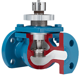
What else makes the HI-100™ unique? The seating element within the valve, a spherical ball, is contained by a cage which positions it relative to the downstream seat by means of linear travel, so there are no close clearances between the cage, ball, and seat. This allows the valve to operate both smoothly and efficiently regardless of temperature, and/or in fluids that carry suspended particles, such as light slurries.
The valve’s Quick Change Trim feature offers further benefits, trim is replaced in-line without use of special items. Furthermore, the interchangeability of the upstream and downstream seats and wear bushings mean an extended valve life, and therefore lower costs and less downtime.
Other features and benefits include: low operating thrust; manual, pneumatic, electric, and hydraulic actuation; weld end, flanged or custom end prep; temperatures from -425°F to 1900°F, and more.
Have questions or want more information on the HI-100™ severe service control valve? Contact DFT today or download our full Control Valve catalog to see what options we offer.


