Category Archive: Uncategorized
Why Sanitary Check Valves Are Important
Sanitary check valves function by preventing fluid backflow, which can cause contamination of products during any manufacturing process that involves fluid passage between systems. These valves are used throughout a wide range of industries that work with pressurized fluids and must adhere to strict sanitary standards, including chemical processing, pharmaceutical manufacturing, and food and beverage processing.
What Are Sanitary Check Valves?
Sanitary check valves are a type of specialized valve designed to only allow fluid to flow in one direction, preventing backflow or the reversal of fluids. They are typically made with durable stainless steel materials and are polished externally and internally to meet or exceed 3A sanitary standards.
Sanitary check valves are beneficial because they do not require air, electricity, or manual intervention from an operator to open or close. Instead, they rely on forward flow pressure to push open the disc away from the seat. When that pressure is removed, the disc returns to its original position to keep the valve closed. Backflow pressure also forces the disc to close.
Sanitary Check Valves and Their Properties
Sanitary check valves prevent liquid backflow and protect compressors and pumps, making them an ideal solution for material distribution or processing systems. To prevent contamination, sanitary check valves have a tight seal to stop the reversal of fluids and create a one-way system.
When adding or replacing sanitary check valves for your processing systems, look for the following key properties:
- Dependable construction. Sanitary check valves should last long without failure, degradation, or frequent replacements. These valves should feature reliable designs and material compositions to ensure longevity and minimal maintenance.
- Tight seal to prevent leakage. For sanitary applications in food and beverage processing and other industries, the potential for product leakage must be eliminated. You can address these hygienic concerns by selecting sanitary check valves that ensure tight seals.
- Internal smoothness. Sanitary check valves are typically constructed with 316L stainless steel that has been polished internally to prevent buildup. There should be no internal edges or rough surfaces that could allow impurities or buildup to stick and cause metal degradation. There also shouldn’t be any internal crevices where potential contaminants can accumulate and cause unsanitary conditions.
Check Valve Orientation: Horizontal, Vertical Flow Up, or Vertical Flow Down
DFT® manufactures two styles of spring-assisted sanitary check valves that are clean-in-place and meet 3A standards. They are available in ½” to 4” line sizes and come with a standard 32 Ra internal surface finish, or optional 15 Ra internal finish.

These valves are commonly used in applications requiring the evacuation of process pipelines, such as instances involving product drainage or recovery. Horizontal sanitary check valves are also useful in clean-in-place operations and applications requiring air agitation for products in tanks or pipelines.
DFT DSV® Vertical Valves: These valves can operate in both vertical flow up and vertical flow down as well as horizontal positions. They can also be used in horizontal piping when self-draining valves are not required.


Industrial Applications of Sanitary Check Valves
Industries such as chemical processing, pharmaceuticals, food and beverage processing, and others that work with pressurized fluids frequently use stainless steel sanitary check valves. They are used in applications that require clean or sterile conditions. Standard features are clean-in-place, crevice free, high polished surfaces, manufactured to high standards and are commonly certified 3A.
They are used to control fluid movement in systems such as:
- Sterile water systems
- Dairy processing
- Brewery and distillery processes
- Purified water systems
- Production of specialty chemicals
- Sterilization systems
- Manufacturing of lotions, creams, gels
- And many more applications
DFT® Valves’ Sanitary Valve Product Offerings and Capabilities
Eliminating the risk of backflow is critical for industrial processing systems across various industries. Get the job done with sanitary check valves you can trust. Our DSV® sanitary-style check valves are built for optimal reliability, quality, and durability. Specify DFT® sanitary check valves that will enhance your facility’s efficiency and safety.
For more information about our line of sanitary check valves, check out our catalog today.
Metal Materials of DFT® Valves
When it comes to industrial applications, selecting the right valve material is of the utmost importance to ensure process reliability, efficiency, and safety. For over 80 years, DFT® has been at the forefront of high-quality valve manufacturing for diverse industries. We specialize in durable, high-performance check and control valves designed to operate in various temperature ranges and pressurized environments while preventing reverse flow, water hammer, and leakage. Our expert team can help you select the right valve and valve material to best support optimal performance and longevity in your equipment and systems.

Valve Materials
At DFT®, we work with an extensive selection of metal materials to meet the specific needs of different industrial applications. Our check valve material options include the following:
- Stainless steel. Available in multiple grades, this durable material consists primarily of iron, chromium, and varying percentages of other elements such as nickel and molybdenum. With its strength and resistance to corrosion, stainless steel is suitable in a wide range of applications, particularly for environments in which rust or staining would otherwise be likely to occur.
- Duplex stainless steel. This stainless steel variety combines both ferritic and austenitic steels into its composition, with higher amounts of nitrogen, chromium, and molybdenum than standard stainless steel. This strong, highly corrosion-resistant material is well-suited to rugged applications in industries like the oil and gas sector.
- Carbon steel (WCB). This carbon steel variety is a strong yet economical material option comprised mostly of iron and carbon. Valued for its weldability, it supports diverse industrial applications.
- Low carbon carbon steel (LCC). With less carbon in its makeup than WCB, LCC steel is well suited for applications in low-temperature environments. While it has good ductility, its lower carbon content equates to a moderately strong steel.
- Nickel-aluminum-bronze. A particularly strong alloy of copper with aluminum and nickel, this material is resistant to cavitation as well as erosion. Its ability to withstand corrosion in seawater environments lends it to marine applications.
- Alloy-20. This alloy of iron, nickel, chromium, along with molybdenum and copper, provides superior resistance capabilities to a range of substances and circumstances. Alloy-20 resists physical deterioration like pitting, stress cracks, and crevices as well as corrosion due to sulfuric acid, making it a top choice for chemical processing applications.
- Hastelloy®. The material composition of this family of alloys is based in nickel, with large percentages of elements like molybdenum, cobalt, chromium, and tungsten. Compared to standard material options, they offer high corrosion resistance against chemicals, high acid substances, and gases at high temperatures.
- Monel®. The beneficial mechanical properties of this nickel and copper alloy give it versatile uses in applications like generating aerospace parts, marine engineering, and processing chemicals. It has exceptional resistance to corrosion, alkalis, and acids.
- Inconel®. Inconel® is a group of strong superalloys, the composition of which has a chromium and nickel base. With strength and integrity even under harsh thermal and chemical conditions, they’re valued for their outstanding corrosion, oxidation, and high-heat resistance. Inconel® materials are indispensable for demanding sectors like chemical processing, aerospace, and power generation.
- Stellite®. With its superior hardness and resistance to wear, erosion, and thermal fatigue, this alloy chiefly composed of chromium and cobalt with some carbon and tungsten is an ideal material for valve components. Its durability supports long life cycles and reliable performance in valves for critical aerospace, oil and gas, petrochemical, and power generation applications.
- Teflon® (Polytetrafluoroethylene PTFE). A brand name for PTFE, Teflon® is a chemically inert material that’s popular for being a non-stick, low-friction synthetic fluoropolymer. In addition to chemicals, PTFE is resistant to high heat, remaining stable as a coating material for everything from gaskets and seals to pots and pans.

Explore the Versatile Material Options Available at DFT®
DFT® is dedicated to quality and innovation, a commitment that’s reflected in our diverse material offerings. We use quality materials in our check and control valves, ensuring that our products can meet versatile performance requirements and stringent industry standards for safe, reliable operations.
Ready to find the right valve solution for your application? Contact us or request a quote for more information, or review our DFT® Pressure – Temperature Ratings and DFT® Valve Selection Chart to identify the ideal valve for your needs.
What You Need to Know About Steam Condensate
In our webinar, Steam Condensate, Important Things to Know, we provide an engaging, informative overview of steam condensate and its critical role in the industry today. The webinar includes a short history of steam condensate, some of the most common problems that arise when utilizing it, solutions to those problems, and a survey of its many modern applications. Below is just an overview of the webinar and we highly suggest watching it in its entirety.
What Is Steam Condensate?
Steam condensate is a liquid that forms when steam transitions from a vapor to a liquid (condensation). During heating processes, condensate forms when steam transfers part of its latent heat energy to the product or line being heated. The saturated steam used in heating applications gives up most of its total heat as latent heat. The rest of the heat in the steam is retained as sensible heat in the condensate.
Condensate Recovery
When condensate forms during heating, systems engage in condensate recovery to recycle this liquid and its sensible heat content, directing it to other processes. As a result of this reuse, facilities benefit from increased energy savings, in addition to reduced make-up water use and chemical treatment.
Specific benefits of steam condensate recovery include:
- Cost savings: Many processes can make full use of condensate, making it a valuable resource whose recovery can save money over time.
- Compliance with effluent restrictions: Some regions may not allow high-temperature effluent to be disposed of in the public sewer system due to potential system damage and environmental impact. In these cases, effluent requires additional cooling processes, which cost facilities more money. Repurposing condensate reduces high-temperature effluent discharge, helping facilities adhere to local restrictions and minimize additional costs.
- Reduced water changes: Minimizing make-up water use means that facilities won’t incur additional spending for water.
- Lower energy consumption in boilers: By transferring condensate to a boiler’s feedback and reducing the need for blowdowns, boilers retain more thermal energy.
- Improved boiler output: When using cooler feedwater, boilers experience a reduced steaming rate, forcing the boiler to consume more energy to heat the water and less to create steam. However, using high-temperature condensate improves the efficiency and output of the boiler.
The History of Steam Condensate
The history section of our webinar discusses the origins of steam research, beginning with Thomas Savery, who invented the first steam engine in England at the end of the 17th century. He developed and patented it for use in pumping wells in 1698. Thomas Newcomen would later refine that invention in 1712, adding water tanks and pump rods so that deeper water mines could be accessed with steam power. In 1778, James Watt further built on these discoveries, employing a gearing system that allowed a steam engine to drive a flywheel to produce rotational power, spurring the development of the steam locomotive.
These inventions, all originating in England, would become the catalyst for the Industrial Revolution and shape the world as we know it today, with steam power playing an instrumental role in a wide range of industries—including mining, chemical processing, petroleum production, textiles, pulp and paper production, and, most importantly, power generation.
The Basics of Steam Condensate
The webinar then describes the basics of steam condensate, answering the question: Why steam? The main advantages of steam stem from its high efficiency and ease of transportation and control, which make it an ideal medium for heat transfer. Steam power is easy to create due to the abundance of water and wide range of heating options available; simply by managing the temperature and pressure of steam, it can be used for much of the work that powers the industrial world.
The three biggest users of steam power today are the power generation, pulp and paper manufacturing, and chemical processing industries; in these sectors, steam is used for all manner of jobs, including automation, dilution, fractionation, quenching, mechanical drive, and stripping.
Common Issues With Steam Condensate
There are some challenges involved in using steam condensate, however. For instance, it’s important to maintain high-quality steam to prevent a variety of pipe and valve issues, as low-quality steam can reduce heat-transfer efficiency by as much as 65%. Also, if CO2 combines with steam condensate, the formation of carbonic acid and CO2 gas may occur, which can cause rapid corrosion. Luckily, this can be managed through the use of steam traps, which keep water separated from the steam. Engineers and plant managers must also consider the line sizing of pipes to prevent condensate collection, as well as the location and configuration of equipment, the insulation methods used, and the types and quality of different valves used for different applications.
Steam Condensate Q&A
Below, we’ll delve into some of the most common questions we receive regarding steam condensate.
Q: Do you propose using traps for all piping loops with low points in offsite piping?
A: Yes. The condensate must be removed from the lines to prevent water hammer or corrosion of the piping itself.
Q: Can you share some guidelines for specifying cracking pressure? Is there a tool one can use?
A: It’s best to work directly with a manufacturer to pinpoint the best low cracking pressure options for your specific application. In-line (silent) check valves typically have a cracking pressure of approximately 0.5 psi. Depending on the condensate return piping layout, a standard cracking pressure (CP) valve may allow excess condensate to accumulate. In these scenarios, a lower CP is ideal; options will vary from manufacturer to manufacturer. At DFT, we offer solutions that allow for a CP as low as 0.1 psi.
Q: Are there any formulas or tables available for steam pipe sizing?
A: We recommend the reference handbook, “Crane Technical Paper No. 410.”
Q: Are low cracking pressure check valves only necessary in certain types of steam systems?
A: Low cracking pressure valves should be used for condensate return lines, not main steam lines. Also, low CP valves will help reduce the accumulated condensate in return lines.
Learn More About Steam Condensate With DFT Inc.
Steam condensate and its recovery can benefit facilities in multiple ways. By reducing waste and recycling condensate for boilers and other processes, you can benefit from increased energy efficiency, lower resource consumption, optimized boiler performance, and reduced overall costs.
Want to learn more about steam condensate and the advantages of steam condensate recovery? We discuss all of these matters and more in our comprehensive online webinar and the multiple slides accompanying the presentation. View DFT’s prerecorded webinar today.
Check Valves in Universities
There are approximately 4,000 colleges and universities in the USA that host thousands of students, faculty members, and guests every day. These university campuses comprise many buildings, and the larger universities may have hundreds of structures. In all cases, these buildings require heating and cooling that must be properly constructed and maintained.
In most instances, the buildings do not have their own individual heating and cooling systems. Universities tend to have collections of buildings in close proximity to one another. This is an ideal structure for implementing Combined Heat and Power/District Energy Systems.

What Is a District Energy System, and What Role Do Check Valves Play in These Systems?
A District Energy System typically has a central energy plant that generates steam, hot water, and chilled water. The steam is typically produced by a boiler system for heating water. Steam and hot water are distributed through a piping system to campus buildings, providing heat. The central energy system may also have a chiller plant that produces and distributes chilled water to campus buildings for cooling purposes. The heating systems and cooling systems are closed-loop systems that add to their efficiency. District Energy Systems are much more economical and efficient compared to individual heating and cooling systems in each building.
District heating systems typically include the following sections:
- Central Combined Heat and Power System
- Piping distribution system
- Buildings that receive steam, hot water, and/or chilled water
The Role of Check Valves
A Check Valve is a valve that is designed to allow fluid to flow in only one direction. Check Valves prevent fluid from flowing backward in a system. They are common throughout all these systems and play an important role in providing protection to pumps and compressors, as well as preventing reverse flow and water hammer.
Let’s explore the role of Check Valves in Natural Gas delivery systems (gas), Boiler Feed Water systems (water), Boiler Condensate systems (steam to hot water), and general piping systems (hot water and chiller water).
Natural Gas Delivery Systems
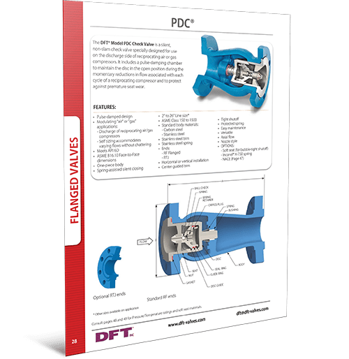
The majority of District Energy Systems use Natural Gas as their fuel source. Natural Gas must be delivered to the Central Plant to heat the boilers to produce steam. DFT® produces a very special Check Valve called the PDC® (Pulse Dampening Chamber), used in Natural Gas compressor stations on reciprocating compressors that maintain the system pressure required to deliver Natural Gas to the Boiler Systems of the District Energy Systems.
Steam and Boilers
Before hot water can be produced for distribution to university buildings, steam must be generated. Steam is generated by boilers. Boilers require a fuel source (natural gas) and water.
Below is a schematic of a Boiler section. Please see the top of the schematic in the section titled Raw Water Make Up. This is where Boiler Feedwater is introduced to the system. This is typically high-pressure water and requires special severe service Check Valves to prevent this high-pressure water from flowing backward out of the Boiler.

DFT® produces a special check valve called the WLC® Boiler Feed Check Valve that is ideal for this application.
Boiler Feedwater Systems
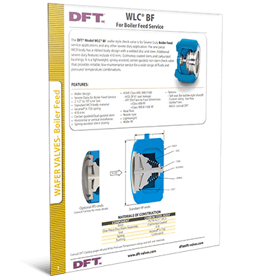
Boiler feedwater systems are challenging due to the potential for high pressure and temperature. DFT® has designed the WLC® Boiler Feed Wafer Style Axial Flow Non-Slam Check Valve that provides excellent performance and protection in boiler feedwater systems. This valve can handle pressures up to 3,705 PSI and temperatures up to 800°F.
DFT® can also offer the Excalibur® or GLC® Check Valve designs if flanged construction is required.
Boiler Condensate Systems
The steam produced in many District Energy System Boilers is in a closed loop system, which means after the steam is used to heat water for distribution, the steam is returned to the boiler at the end of its cycle. Typically, that steam begins to condense back into water and is returned via the Condensate Return Lines. Please see the Top Right section of the schematic titled Condensate Return.
Just as with other portions of a closed-loop system, the fluid is meant to travel in one direction only. Condensate lines are typically smaller in diameter and have lower pressure than Boiler Feedwater lines. DFT® produces smaller Check Valves called the SCV® with threaded end connections that are ideal for Condensate lines in Boilers.

Condensate return systems are integral to boilers. These systems tend to operate at lower pressures and temperatures than feedwater applications. They also tend to have smaller diameter piping. The SCV® can handle pressures up to 2,570 PSI and temperatures up to 510 °F depending on the materials of construction and Cold Working Pressure ratings.
The SCV® provides excellent performance and protection in boiler condensate systems.
DFT® has many types of check valves designed for use in steam and steam condensate systems, depending on the size, flow, and temperature of the application.
We have explored several different Check Valve applications, including Natural Gas delivery, High-Pressure Boiler Feedwater, and lower-pressure steam to condensate return. Once the hot water is generated, it is ready for distribution in the university piping system.
General Piping Systems
Water in piping systems presents its own challenges. The main challenge is how to prevent Water Hammer. DFT® makes Axial Flow Spring Loaded Silent Check Valves. These specially designed valves are designed to eliminate and/or greatly reduce water hammer.
Water hammer is generally recognized as a banging or knocking sound inside the pipes after a pump shuts down. The shocks of this phenomenon can damage pumps, pipes, and surrounding equipment over time, resulting in leaks, corrosion, and poor system operation. By preventing these shock waves, silent check valves eliminate the substantial damage that would otherwise occur throughout the system due to water hammer.
Installing DFT® Axial Flow, Spring-assisted, Non-Slam Check Valves results in safe and silent operation of the hot water and chilled water piping distribution systems. No rattling of pipes, no damage to equipment. When installed properly, due to the silent nature of these valves and the prevention of Water Hammer, you will never know they are there.
What sets DFT® check valves apart from other check valves is the engineered spring-assist technology that prevents reverse flow, reduces the potential for water hammer and vibration, and protects pumps and other high-value equipment. Additionally, the reliability, low maintenance, and long service life provide long-term savings and superior performance.
DFT® makes many styles of check valves that can be used in piping systems. The choice will depend on the diameter of the piping systems, the required end connections (Flanged, Butt Weld, Wafer Style, or threaded style), and the materials of construction.
Download specification sheets of the different styles of DFT® Axial Flow Non-Slam Silent Check Valves from our resource library, or contact us to discuss your needs.
DFT® Announces CAD and 3D Model Files Platform
DFT® is proud to announce the launch of our new CAD File platform!
You can now download DFT® Check Valve CAD files in multiple formats directly from our online product catalog!
The platform, which is powered by TraceParts® a world-leading digital engineering 3D content company, has DFT® CAD and 3D model files available when you need them, 24/7.
Start expediting your design projects today by spending less time modeling with this accurate and high quality file platform.

How does it work?
Once you find your check valve on the DFT® website online product catalog, determined by size/style/class specification, just click on the “3D” link to then choose what type of CAD file format you need.
How to get a CAD File:
- Search for your check valve by product code on the DFT® online catalog or Find your check valve by style/size/class specification, then navigate to the product code page
- Click on the “3D” link located on the right side of the page
- Select the CAD format you require from the dropdown menu
- Click on the “Download” button
At DFT® we strive to make your procurement journey an easy one. Please feel free to contact us if we can assist you in any way.
Highlights
- The ability to see all catalog offerings online
- The ability to drill down to specific materials/wants/needs
- The ability to download 2d/3d files (list all file types from TraceParts) available on-demand
| Available Files Types | ||
| 3D XML | GStarCAD | Revit Family File (RFA) |
| 3MF | HOOPS | SOLIDWORKS |
| AMF | HiCAD (>=2011) | STEP AP203 |
| Acis 6.3 | IGES | STEP AP214 |
| Alibre Design | IRONCLAD | STEP AP242 |
| Animated GIF | Inventor | STL |
| AutoCAD (DWG) - 2D | Inventor LT | SketchUp |
| AutoCAD (DWG) - 3D | JPG | Solid Edge |
| AutoCAD MEP | JT | SpaceClaim |
| BMP | KOMPAS-3D (>=V15) | T-FLEX |
| BricsCAD (DWG) - 2D | KeyCreator | TENADO CAD 3D |
| BricsCAD (DWG) - 3D | Mechanical Desktop | TIF |
| CATIA V4 | NX (*.x_t) | Three.js |
| CATIA V5 | OBJ | TopSolid (< v 7.0) |
| COLLADA | OFF | TopSolid (v 7.8) |
| Creo | TurboCAD | |
| DXF - 2D | PDF 3D | Universal 3D |
| DXF - 3D | PLY | VDA-FS |
| DesignSpark Mechanical | PNG | VRML |
| DraftSight | PRC | VTK |
| EMF | Panda3D | VX CAD/CAM |
| FUSION 360 | Parasolid 11.1 | WMF |
| GIF | Pro/Engineer Neutral | ZW3D |
Choose DFT® for Your Check Valve CAD Files
At DFT®, our experienced and knowledgeable valve experts are available to help you find the ideal solution for your model file needs. Check out the following resources to learn more about our valve solutions and how they benefit a wide variety of industries:
- Check valve catalog and brochure
- Control valve catalog and selection eBook
- Application Success Stories
For additional information about our valve products and services, contact us or request a quote today.


