Category Archive: Check Valves
Is Your Check Valve Oversized for Your Application?
Check Valve Oversizing: Why Bigger Valves Create Bigger Problems

Oversizing a check valve is one of the most common and costly mistakes made during valve selection. While it might seem safer to choose a larger valve, doing so can actually create a chain reaction of performance and reliability issues.
When a check valve is larger than the application requires, there often isn’t enough differential pressure to keep the disc fully open and stable. Instead of operating smoothly, the disc can begin to flutter, rapidly and repeatedly opening and closing due to flow-induced vibration. This constant movement places unnecessary stress on the valve’s internal components.
Over time, disc flutter causes wear on the disc, hinge, seat, and body. The result is shortened valve life, unexpected maintenance, and higher long-term costs. In more severe cases, oversizing can also contribute to noise, pressure surges, and even damage to downstream equipment.

How Check Valves End Up Oversized
Most oversizing issues come from selecting a check valve based only on nominal pipe size. While pipe diameter matters from a mechanical standpoint, it doesn’t tell the full story of how a check valve actually behaves in service.
Unlike isolation valves, check valves depend on flow velocity and differential pressure to operate properly. When a valve is selected simply to match the pipe size, it may never reach its fully open position under normal operating conditions. That not only compromises performance, but also increases upfront costs as larger valves are more expensive to purchase, install, and maintain.
Size for the Application, Not the Line
A core principle of good check valve selection is simple: size the valve for the application, not the pipe. Proper sizing ensures that flow velocities are high enough to fully open the disc and keep it stable across all expected operating conditions.
Treating a check valve like an on/off valve ignores the fluid dynamics that govern its performance. When sized correctly, a check valve operates smoothly, minimizes chatter and delivers predictable pressure drop.
The real advantage is longer service life and reliable, predictable performance.
Application Factors That Matter
To determine the correct check valve size, several application specifications must be considered, including:
- Normal, minimum, and maximum flow rates
- How the flow behaves-steady, intermittent, or highly fluctuating
- Fluid properties such as density, viscosity, and compressibility
- Startup and shutdown conditions, where low or reversing flows are common
Systems with a wide range of flow conditions, often referred to as high turndown applications, present certain challenges. In these cases, a standard pipe-sized valve may be too large to remain stable at low flows. A smaller or sized check valve is often required to maintain adequate flow velocity and prevent flutter at full operating range.
Why Experience Matters in Valve Selection
An experienced check valve manufacturer or application engineer looks beyond pipe size alone. They evaluate flow conditions, operating scenarios, and valve dynamics-before making a recommendation.
Less experienced suppliers may default to pipe-matching practices, increasing the risk of oversizing and early failure. True subject-matter experts understand how valve geometry, flow behavior, and system demands interact, and they guide customers toward solutions that balance performance, reliability, and total lifecycle cost.
If you have questions about check valve sizing or want help evaluating your application, contact DFT to learn more about our DFT’s Check Valve Sizing Program.
You can also download our Check Valve Sizing eBook or watch our DFT Sizing Webinar to learn more about proper selection practices.
You can also download our eBook on Check Valve Sizing from the link below:

History of the ‘Basic-Check’ Valve
Since its initial development, the check valve has evolved from a classified request from the U.S. Navy to becoming a staple in flow control systems, allowing operators to easily stop reverse flow and water hammer while providing tight metal-to-metal closure. Some of the first all-stainless steel valves were engineered for use with cryogenic liquids and facilitated the development of the first nuclear weapons. Since then, check valves have grown into a fundamental element of fluid system design across a range of applications.
Roots in Reliability: Durabla® & the U.S. Navy
Originally known as Durabla Manufacturing Company, which manufactured pump valves, Durabla developed a reputation early on in the industry for both superior quality and innovation. Eventually, the company would split into Durabla Fluid Technology (DFT®), which focuses on check valves, and Triangle Pump Components Inc., another division dedicated to reciprocating pump components production.
Throughout the 1920s and 1930s, Durabla nurtured a strong relationship with the U.S. Navy, which eventually requested a classified internal check valve design that could hold up in cryogenic temperatures.
A Classified Beginning: The Birth of the Basic Check Valve
With the Government’s request for a unique temperature-resistant valve for the then-classified Manhattan Project, the concept of the Basic-Check Valve was born. This iteration of the valve could withstand some of the lowest temperatures and provide tight closure to keep equipment functioning properly in a cryogenic environment.
The uniquely durable and lightweight disc-shaped design of the Triangle Pump pump valves enabled them to last longer, which led the Military to request a similarly designed check valve that could replace less reliable elastomer valves for use with cryogenic liquids.
Declassified & Delivered: Post-War Innovation
By the early 1950s, the U.S. government had disclosed the Manhattan Project to the public, allowing for further development of DFT®’s proprietary check valve design. The basic check valve design worked across numerous applications involving extreme temperatures. Unlike elastomeric designs, these check valves could withstand high and low temperatures in many commercial and industrial environments, making them a standard option for various industries.
Legacy & Evolution
In the years since its declassification and widespread commercialization, the basic check valve has evolved in different ways to meet applications’ varying needs.
For example, some DFT® clients have requested a valve that would remain closed until it reached a specific pressure level, which led DFT® to develop a restrictor check for use in steam systems and other applications. This involved installing a stronger spring in the existing basic check valve design. The reliable design of the basic check valve also contributed to a vacuum breaker design that could prevent steam leakage in textile systems and ensure the valve opened reliably.
Today, the versatility and overall quality of DFT®’s basic check valve design has become a go-to solution in the industry – setting DFT® apart for the company’s consistent quality, reliability, and performance. You can now find these valves in the following:
- Autoclaves
- Cooling towers
- Cookers
- Chemical lines
- Evaporators
- Hydraulic lines
- Refrigeration
- And more
Innovation over the years
DFT® continues to innovate with different variations of the basic check valve design. One such innovation entailed the development of our SCV Check Valve, which consolidates two components into a single one to prevent water hammer and provide tight closure in 1/2″ to 3″ pipes. Through this innovation, the company continues to honor its roots by ensuring the ongoing quality and reliability of DFT®’s check valve design.
Reliable Check Valves From DFT® Inc.
What began as a little-known component for an exclusive research enterprise has since grown into a globally ubiquitous product. DFT®’s basic check valve continues to be installed and used in many systems, with multiple iterations of its design across several high-quality DFT® products. Whether you need one of our in-stock items or a special order to meet your unique application requirements, we’re here to direct you toward the right solution.
Want to find out more about our check valves and control valves? Contact us today to speak with a member of our team or request a quote for a standard or custom order.
Q&A from DFT’s Webinar: Check Valve Solutions for the Mining Industry
Following our webinar, Check Valve Solutions for the Mining Industry, we’re sharing some of the questions from the audience along with our detailed answers. In the webinar, presented by Arie Bregman—who brings nearly five decades of experience in the valve industry—we explored the role of check valves in dewatering, slurry transport, and preventing backflow. We covered best practices for sizing check valves correctly to ensure optimal performance in mining applications, strategies to prevent water hammer and mitigate pressure surges with non-slam check valves, and how proper valve selection can reduce maintenance while improving operational efficiency. Arie’s technical expertise and commitment to industry education make him the ideal guide for these critical topics. If you missed the webinar, you can now watch it on demand on the DFT® website—just [click here].
Q: Wont Gravity help close a swing check valve in a vertical flow up application?
A: Gravity will absolutely close a swing check valve, after the flow has already stopped. This will cause water hammer to occur every time. The Axial Flow design incorporates an internal spring that opposes the flow and will start closing the valve as the flow rate starts to drop due to pump shut down. If the valve has a cracking pressure of 0.39 psi (as I used in our sizing example), then when the flow rate results in a differential pressure through the valve of less that 0.39 psi the valve will be closed. Because flow hasn’t reversed you will avoid the hydraulic shock and resulting shock waves with the fluid inside the pipe.
Q: In a low flow application can you remove the spring in an axial flow check valve?
A: Yes you can remove the spring in an axial flow valve, but doing so will negate the benefit of water hammer reduction/elimination. You will also limit the installation orientation options when the spring is removed. The valve will continue to work because the reversing flow will now close the valve. This means that the valve will continue to function with a missing or broken spring, you just have to understand that the advantage of water hammer reduction/elimination of the axial flow design is now lost.
Q: How low of a cracking pressure spring can you specify?
A: Cracking pressure lower limits are a function of the size of the valve. Smaller valves have very light weight discs and so small screwed end valves from ½” up to 2” can tolerate a 0.1 psi spring while over coming any internal friction factors and still closing the disc against the seat. There are many steam condensate applications that need such a low cracking pressure, and those valves work very well in that environment. From about the 3” line size up to about an 8” line size the lower end of cracking pressures is about 0.25 psi. In all cases the factory should be consulted regarding lighter spring selection options. There is no one size fits all rule here, internal friction, disc/stem weight all play a role in determining the lower end of check valve cracking pressure.
Q: How does vertical flow down effect valve selection?
A: Vertical flow down is another unique application orientation that requires factory consultation. The weight of the disc/stem subassembly coupled with the spring selection all play a role coupled with any desired static fluid head that may need to be retained above the valve. The factory team understands these issues very well and are on hand to work with you to help you select the right valve for these applications.
Q: Is axial flow check valve suitable for slurry application
A: Yes, Axial Flow check valves can be used in slurry applications. The main concern with slurries would be the maximum particle size that would be contained within the slurry. Maximum particle size is always dependent on the nominal valve size and the amount of opening between the disc and seat that is available for the particles to pass through. Generally speaking, the amount of lift in an axial flow check valve is about 1/4 of the NPS, so a 4″ valve might have about 1″ of lift. The maximum particle size would be about 1/2 of that to allow it to pass easily through the valve.
Q: Are there any applications or process conditions where axial flow check valves are prone to damage, such as slugging?
A: High concentrations (above 25%) of large particles whose size exceeds 10% of the valve Nominal Pipe Size could be problematic for axial flow valve designs because of the potential for these particles to cause clogging of the valve. Lower concentrations of approximately 10% in a aqueous slurry should be able to flow through the valve with no major issues.
Q: In the case of higher solids content (20-30% by weight) do these valves perform well? The spring is not affected by the solid particles?
A: 20-30% solids whose maximum size is less than 5% of the valve NPS should not cause major problems. In all cases the spring is on the down stream side of the disc and is protected from direct impingement by solids in the media flowing through the valve. I wold urge you to discuss these applications with the factory to get their guidance early on in the specification process. All applications have unique parameters, and it is always difficult to give a one size fits all answer when it comes to solids in the flow stream.
Q: Would two valves back-to-back work? sometimes the process specifies two of them for safety
A: 2 valves back-to-back should work just fine. I would recommend that the 2 valves be spaced apart by at least 5 times the NPS to allow for the flow to restore to a more laminar flow as it enters the second valve. Excessively turbulent flow will cause unbalanced forces to act on the internal trim components of the second valve potentially leading to vibration related damages to occur.
Q: What’s the most challenging aspect of manufacturing these valves? How do you manage performance variability caused by assembly variation?
A: Axial flow check valves are relatively simple designs that are not too overly complex to manufacture. The manufacturing tolerances that impact the amount of opening of the valve and the space provided for the spring may have a very minor impact on the flow capacity (Cv) of the valve as well as a small impact on the cracking pressure of the valve. Generally, the Cv variability will be less than 1% of the stated value while the cracking pressure could vary by +/- 5% of the nominal published value.
Have questions about your mining applications? We’re here to help. Contact us today to discuss your needs. https://industrial.dft-valves.
Check Valve Solutions for the Mining Industry: Webinar Overview
 Mining is one of the oldest industries on Earth, but its challenges remain as modern as ever. At DFT®, we recently hosted a webinar titled Check Valve Solutions for the Mining Industry, led by Arie Bregman, who brings nearly five decades of experience in the valve industry. This session explored how the right check valve solutions help mines operate more safely, efficiently, and reliably—while avoiding costly problems like water hammer.
If you missed the original webinar launch, you can watch it on demand here. Below is an overview of what we covered.
Mining: A Global, Evolving Industry
Mining is a $3.5 trillion USD global industry that supplies essential raw materials for modern life—from precious and non-precious metals to lithium, coal, bitumen, salts, and gemstones. Extraction methods vary widely, from open-pit mining to deep underground mines, subsea mining, placer mining, and solution mining.
Each method has unique challenges, especially when it comes to water management, ore processing, and tailings disposal—all areas where reliable check valve solutions are critical.
Water Management: A Central Challenge
Both open-pit and underground mines must contend with significant water inflow—from groundwater, rain, or geological formations. Removing this water involves powerful pumps and extensive piping systems. A defining feature of these systems is vertical flow-up piping, where water must be lifted hundreds or thousands of feet to the surface.
Unlike horizontal systems, vertical pipelines require check valves that don’t rely on gravity to close. Without the right valve design, reverse flow during pump shutdown can create water hammer—a violent hydraulic shock that can damage equipment, increase maintenance costs, and pose serious safety risks.
Why Axial Flow (Silent) Check Valves?
DFT’s axial flow check valves (also known as silent check valves) are designed specifically to mitigate water hammer. Their spring-assisted closure ensures they react immediately to flow reversal, preventing pressure surges. They work in any orientation—horizontal or vertical—making them ideal for the unique vertical piping demands of mining.
Ore Processing and Refining Applications
Once ore is removed from the mine, it is crushed, concentrated, and refined. Processes like flotation, leaching, and electrowinning use chemicals and fluids to extract valuable minerals such as copper or gold.
These systems often feature vertical flow, corrosive solutions, and abrasive solids—all of which place demands on check valve performance:
- Materials: DFT valves are available in stainless steels (316 SS, 410 SS) and high alloys (Monel, Hastelloy, Titanium) to handle corrosive and abrasive media.
- Customization: Options for hardened trim (e.g., 410 SS, Stellite) increase resistance to erosion in slurry or acidic environments.
- Oxygen Service: Gold refining uses oxygen, which requires special materials, cleaning, and certification to ensure safety and purity.
Tailings Management
Tailings—slurries of rock fines and residual chemicals—are a by-product of ore processing. Moving these abrasive, high-volume flows requires large pumps and equally robust check valves.
DFT axial flow valves in wafer or flanged designs are widely used for these applications. Options include:
- Wafer Style: Compact and cost-effective, conforming to standards like API 594 and EN 558.
- Short Pattern Flanged: One-piece bodies for strength, with options in carbon steel and stainless steel.
- Custom Materials: Trim options such as 410 SS or higher alloys for erosive or corrosive service.
Special Considerations: Subsea and Solution Mining
Mining isn’t limited to land. Subsea mining brings its own challenges, including saltwater corrosion and high ambient pressure. Here, materials like Monel, Nickel Aluminum Bronze, and Titanium become important. DFT offers extensive experience supplying valves in these high-performance alloys.
In solution mining—where chemicals are injected into ore bodies to dissolve minerals in place—pumps and check valves must handle harsh fluids while preventing reverse flow and water hammer.
Sizing Your Check Valves Correctly
One of the most important takeaways from our webinar is proper sizing. It’s not enough to match valve size to pipe diameter. Flow rates, pressure drop, and cracking pressure all matter. Undersized or oversized valves can:
- Fail to open fully at low flow, leading to chatter and premature wear.
- Create excessive pressure drop or noise at high flow.
DFT provides Cv values and detailed sizing guidance to ensure the valve works optimally in its specific application—reducing maintenance costs and improving reliability.
Why Choose DFT® Check Valves?
DFT® offers a wide range of axial flow check valves, engineered for the demands of mining:
- Axial flow design that eliminates water hammer
- Sizes from ½” through 42″
- Wafer and flanged styles, with end connections meeting ASME, EN, and API standards
- Materials from carbon steel to stainless steel, Monel, Inconel, Hastelloy, and Titanium
- Custom sizing support to optimize performance in your unique application
- Full QA documentation and certifications for specialized service
Watch the Webinar On Demand
If you missed Check Valve Solutions for the Mining Industry or want to review the details, you can watch it on demand here.
Have questions about your mining applications? We’re here to help. Contact us today to discuss your needs.
What are the Types of Check Valves Used in the Gas Industry?
Check valves are used in pipelines, hoses, and tubing to prevent backflow of liquids and gases. In the gas industry, this helps protect equipment from damage, reduce excessive vibration, and maintain steady production.
A major use for check valves is normalizing the flow of gas during reciprocating compressor discharge in long-distance pipelines. Other natural gas production uses include directing gas flow on metering pumps, hydraulic and air lines, pump discharge, and pressure letdown processes. Check valves are also widely used with gases in oil refineries, chemical and petrochemical plants, and manufacturing facilities.
Here, we’ll look at what check valves are, factors to consider when specifying them, and how they benefit gas industry applications.
What is a Gas Check Valve?
 A check valve keeps liquids or gases flowing in a desired direction while preventing them from flowing backward (also called the non-return direction). They are available in many configurations, including threaded, flanged, and space-efficient wafer designs.
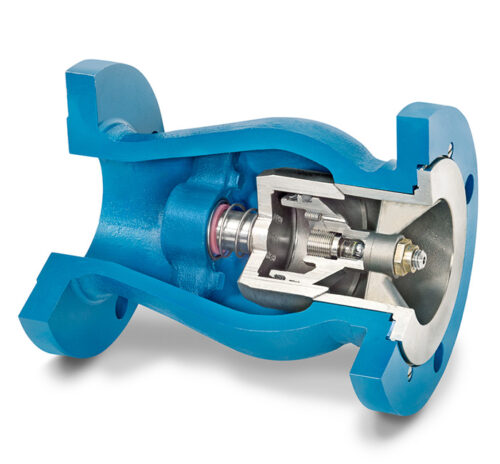
In an axial flow check valve, gas moves parallel to the axis of rotation through the center of the valve. In-line check valves are placed at predetermined points along a pipeline or tubing system. The valve contains a spring-loaded disc pressed against a gasket to keep the valve closed in its default resting state. When sufficient gas pressure is applied to the disc, it opens and the gas flows through. When pressure drops, the disc closes to prevent the gas from flowing back in the opposite direction. A stem and bushing guide the disc to keep it properly aligned. Nozzle-style check valves are a type of axial flow valve designed specifically for use with low-pressure or intermittent flow liquids or gases.
In natural gas production, check valves are critical for reciprocating compressor discharge. DFT® Inc.’s PDC valve is an ideal solution due to its pulse-dampening chamber, which keeps the disc open during discharge, even as pressure and flow rate may vary. It is a nozzle-style valve with durable carbon or stainless steel construction, a Durlon 9000 gasket, Teflon and Rulon guiding elements, and an Inconel x750 spring for durability and a long service life. As a result, the PDC valve is suitable for a range of uses in the oil, gas, and other industries.
Important Specifications in the Gas Industry
Key factors in specifying gas check valves include:
- Gas Characteristics and Composition. This includes fluid viscosity and specific gravity, corrosiveness, particulate matter, and elemental composition, all of which influence valve size and materials.
- Gas Flow Rate. This influences the size and design of the check valve needed, such as threaded or flanged models. High-flow systems often require larger or multiple valves.
- Temperature. Extreme and/or fluctuating gas and ambient temperatures influence decisions about materials, especially for thermal shock resistance.
- Pressure. Check valves are rated for different operational and maximum pressures in the overall system and in the specific location of the valve.
- Cracking Pressure. This is the minimum pressure needed to open the valve and permit gas flow. If cracking pressure is too high, the valve is harder to open and may slow the flow rate, causing chatter. If it is too low, the time to close the valve increases, since back pressure must overcome forward pressure to close it.
- Operating Environment. This includes horizontal or vertical orientation; accessibility for maintenance in remote locations; gas flow path; vibration, shock, or pulsation in the system; temperatures; and corrosiveness of the environment (e.g., offshore or salt spray exposure).
- Valve Materials. Materials impact the valve’s resistance to environmental conditions and durability over the lifetime of production. They may also affect its ability to stay open or closed for a prolonged time.
- Regulatory Compliance. Check valves used in the oil and gas industry must comply with standards set by the American Petroleum Institute (API), the American Society of Mechanical Engineers (ASME), and the International Organization for Standardization (ISO).
Benefits of Check Valves
Check valve technology benefits natural gas production and other processes that use gases in daily operations in these ways:
- Protecting Equipment. Check valves protect pumps and compressor equipment from damage caused by backflow or reverse flow, ensuring systems operate smoothly and without interruption.
- Minimizing Chatter from Turbulence or Pressure Drop. Properly sized and located check valves minimize chatter from the disc opening and closing repeatedly, which contributes to wear on the valve. Chatter is caused by turbulence or drops in flow pressure, and valves that are oversized or too close to the discharge port may not receive adequate pressure to remain open consistently.
- Preventing Slam and Water Hammer. Using the right size valve protects against slamming and hammering from sudden pressure drops, which can damage equipment and pipes or tubing.
- Low Maintenance. Axial flow valves have no external components which protects them from damage and associated repair or replacement.
- Spring-Assisted Design. The spring-assisted design holds the valve disc closed reliably.
- Versatile Installation. Check valves can be oriented vertically or horizontally.
- Tight Shutoff. The spring and gasket ensure a tight seal to prevent leaks.
- Reducing Downtime. Correctly sized check valves help reduce downtime and expenses associated with equipment maintenance or replacement.
- Custom Sizing. Custom sizing is available for certain applications, pressures, and flow rates.
Gas Check Valves from DFT® Inc.
Check valves play a crucial role in the efficiency, safety, and reliability of gas production, oil refining, and similar operations. DFT® check valves offer superior performance, lower maintenance costs, and reassurance against equipment damage due to backflow.
To learn more, visit our DFT® Gas Transmission page to see our PDC and other gas and oil check valve solutions.


